LCD or Liquid crystal display is a common output device used for embedded, IoT devices, industrial control, and medical devices. To display simple text messages, alert messages and keypad entries from user Alphanumeric LCD or character LCD is easy to use and takes less GPIO from the microcontroller. In general Alphanumeric LCD comes with dimensions of 16×2: which indicates it can display 16 characters per line and two lines (total 32 characters) or 16 x4: which indicates it can display 16 characters per line and Four lines (total 64 characters), also 20×2 and 20×4 LCDs also available from different vendors. This blog shows how to interface 16×4 Alpha-Numeric LCD with Arduino-Uno using the I2C interface.
The pin-out of Alphanumeric LCDs is shown in the below table.
| Pin Number | Pin Name | Functionality |
| 1 | GND | Supply Ground |
| 2 | VCC | Power supply voltage 5V. |
| 3 | VEE | Adjust LCD contrsat |
| 4 | Register Select | RS for Command or Data |
| 5 | R/W | Reading or Write to LCD |
| 6 | LCD_Enable | This pin is used to enable LCD |
| 7-14 | D0 | D0-D7 are data lines for reading and writing |
| 15 | LED+ | Backlight Supply (5V) +ve |
| 16 | LED- | Backlight Supply -ve |
In these LCD modules, there is an LCD controller driver which is responsible for displaying font, setting the cursor address to the character matrix. The important pins used in LCD interfacing are
- Register select (RS): While communicating with LCD using a microcontroller, it has to commands to initialize the LCD and to move the cursor, etc. This mode of LCD operation is called command mode. To display the text LCD should be selected to data mode. The register select (RS) pin is used to keep LCD in command and data modes.
- LCD_Enable: This pin is used to enable LCD display.
- R/W pin: This used to select read the cursor position or write the character to be displayed.
- D0-D7: Parallel data line using which we can send data/ read data from LCD. LCD can be made to work in 4-bit mode or 8-bit mode.
From the above pin-out table, we can understand that to interface Alphanumeric LCD with a microcontroller it needs ten (10) GPIOs in 8-bit mode and up to six(6) GPIOs in 4-bit mode. To minimize the use of GPIOs there are I2C -parallel LCD converters that are available. This module is based on PCF8574 I2C to an 8-bit I/O expander. This module is as shown below.

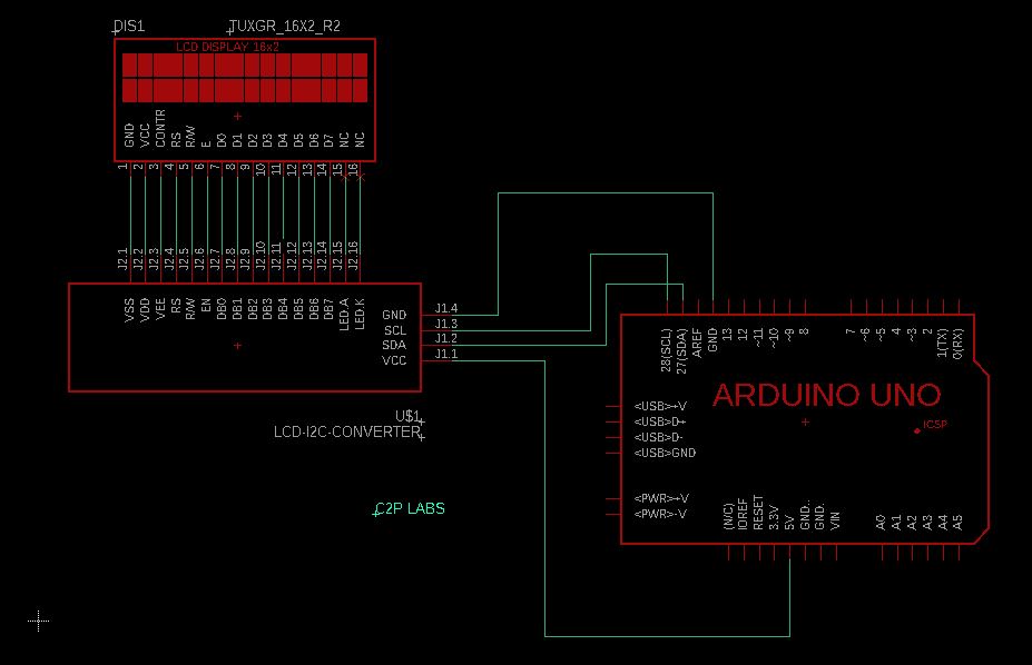
The connection diagram for using the I2C LCD module and 16X4 LCD display and Arduino Uno is shown in the below circuit. I2C pins SCL and SDA are connected to Arduino SCL and SDA pins.
Arduino Program:
#include <Wire.h> // This header file is required for using I2C library
#include <LiquidCrystal_I2C.h> //This is header file for supporting I2C LCD
LiquidCrystal_I2C lcd = LiquidCrystal_I2C(0x3F, 16, 4); //LiquidCrystal_I2C: Constructor take I2C
                                                        //address of the module 0x3F. This address
                                                        //depends on how a0,a1 and a2 are connected.
void setup() {
  // Initiate the LCD module.
  lcd.init();
  lcd.begin(16,4);
  lcd.backlight();

  lcd.setCursor(0, 0);
  lcd.print("C2P LABS");

  lcd.setCursor(0, 1);
  lcd.print("ROBOTICS AND");

  lcd.setCursor(0,2);
  lcd.print("COMPUTER VISION");
  lcd.setCursor(0,3);
  lcd.print ("TRAINING");

}

void loop() {


}
The code snippet shows that we are using the Arduino LiquidCrystal_I2C library which is developed to support I2C LCDs.
LiquidCrystal_I2C(I2C_addr, No_of_cloumn, No_of_rows).
LiquidCrystal_I2C(0x3F, 16, 4): 0x3F is I2C address and 16 cloumns and 4 rows.
setCursor is used to set the cursor position for displaying the text on LCD. The syntax is
setCursor(column, row): Column starts from 0 to 16 and row is from 0 to 3 for 16×4 LCD display.
lcd.setCursor(0, 1): start displaying the text at column 0 of the second row.
