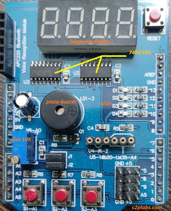
Arduino is a versatile computing platform to work on microcontrollers and embedded systems. It can be used to write programs and run on microcontrollers. These boards comes with on board LED which can be as a hello word Arduino program. To extend the functionality and to interface with external physical world we need do lot of writing with bread board and jumper wires. Multi-function shield is the one comes with rich set of digital input output options to try different input-output devices with Arduino. This comes with the following features.
- It has four LEDs connected to 10, 11, 12 and 13 pins of Arduino
- Four digit seven segment display connect through two 74HC595 serial in- parallel out shift registers
- A piezo-buzzer connect to pin 3, using transistor driver circuit.
- It also has trim pot(10K) connected to Analog-input pin A0.
- Three buttons connected
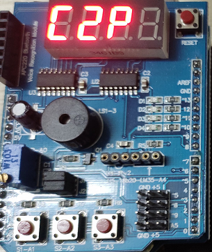
In this blog we use 7-segment display to display C2P. The schematic diagram of four digit 7-segment display connected through 74HC595 is shown in the below pic.
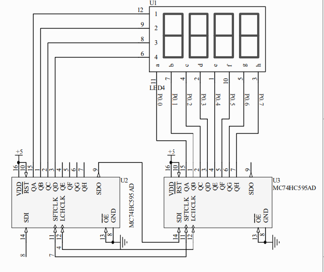
As shown in the schematic, four digit LED 7-segment display is connected to Arduino using two 74HC595 serial to parallel shift registers in cascade connection. In this way of connection clock and latch pins of shift register is shared same IO pins from Arduino. Pin 7 for CLK and pin 4 for LATCH. SDO of first Shift register (74HC595) is connected to SDI for cascaded one. Pin 8 of Arduino is connected to SDI (Serial Data In) of first shift register.
One of the shift register is connected to select pins to select the digitand other is connected to a-g pins of segments. To display characters on 7-segment first we have to select which digit we want to use and send the hex data of character to be displayed.
Seven Segment display( 7-segment display) fundamentals:
Seven segment displays consists of seven LEDs arranged to form rectangular shape digits and alphabets. Each module also consists of eighth LED which is a dot (.).
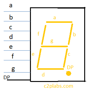
Seven segment displays can be of two types common cathode or common anode. In common cathode module to glow individual LED pin should be made logic HIGH or logic 1. In common anode individual LEDs should be supplied with logic LOW or logic zero. The seven-segment modules used on Arduino multi function shield is Common Anode (CA) modules.
Truth table for Seven Segment display:
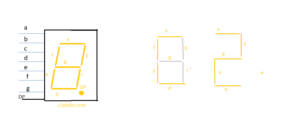
To display a particular character or digit on each segment we have to send appropriate data to segments. Lets discuss about displaying digit 2. To display digit 2, LEDs a,b,d,e,g should glow. As the segment used is common anode logic LOW zero should be supplied to these segments, and all other c,f and dp LEDs should be given logic HIGH [1].
The truth table for displaying zero (0) and “C2P” on seven segment display is shown below.
| Display Digit/Letter | DP | g | f | e | d | c | b | a | Hex Byte |
| Digit-0 | 1 | 1 | 0 | 0 | 0 | 0 | 0 | 0 | 0xC0 |
| Letter-C | 1 | 1 | 0 | 0 | 0 | 1 | 1 | 0 | 0xC6 |
| Digit 2 | 1 | 0 | 1 | 0 | 0 | 4 | 0 | 0 | 0xA4 |
| Letter-P | 1 | 0 | 0 | 0 | 1 | 1 | 0 | 0 | 0x8C |
| OFF | 1 | 1 | 1 | 1 | 1 | 1 | 1 | 1 | 0xFF |
Arduino Program:
#define LATCH_PIN 4
#define CLK_PIN   7
#define DATA_PIN  8


 void SendDataToSegment(byte Segment_no, byte hexValue);

const byte C_HEX  = 0xC6;
const byte TWO_HEX  = 0xA4;
const byte P_HEX  = 0x8C;

byte select_seg1 = 0xF1 ;
byte select_seg2 = 0xF2 ;
byte select_seg3 = 0xF4 ;
byte select_seg4 = 0xF8 ;


const byte SEGMENT_SELECT[] = {0xF1,0xF2,0xF4,0xF8};


void setup ()
{
/* All the pins like latch, clock and data pins are used as output */
  pinMode(LATCH_PIN,OUTPUT);
  pinMode(CLK_PIN,OUTPUT);
  pinMode(DATA_PIN,OUTPUT);


}

/* Main program */
void loop()
{
/* Update the display with the current counter value */
  SendDataToSegment(select_seg1 , C_HEX);
  SendDataToSegment(select_seg2 , TWO_HEX);
  SendDataToSegment(select_seg3 , P_HEX);

}


void SendDataToSegment(byte Segment_no, byte hexValue)
{
  /* Make Latch pin Low */
  digitalWrite(LATCH_PIN,LOW);
  /* Transfer Segmenent data */
  shiftOut(DATA_PIN, CLK_PIN, MSBFIRST, hexValue);
    /* Transfer Segmenent Number  */
  shiftOut(DATA_PIN, CLK_PIN, MSBFIRST, Segment_no );
    /* Make Latch pin High so the data appear on Latch parallel pins */
  digitalWrite(LATCH_PIN,HIGH);
}
#define LATCH_PIN 4
#define CLK_PIN   7
#define DATA_PIN  8


 void SendDataToSegment(byte Segment_no, byte hexValue);


const byte C_HEX  = 0xC6;
const byte TWO_HEX  = 0xA4;
const byte P_HEX  = 0x8C;

const byte SEG_OFF  = 0xFF;

int led1 = 13;
int led2 = 12;
int led3 = 11;
int led4 = 10;

int buzzer_pin = 3;

byte select_seg1 = 0xF1 ;
byte select_seg2 = 0xF2 ;
byte select_seg3 = 0xF4 ;
byte select_seg4 = 0xF8 ;

#define BUTTON1 A1
#define BUTTON2 A2
#define BUTTON3 A3


const byte SEGMENT_SELECT[] = {0xF1,0xF2,0xF4,0xF8};


void setup ()
{
/* All the pins like latch, clock and data pins are used as output */
Serial.begin(9600);
  pinMode(LATCH_PIN,OUTPUT);
  pinMode(CLK_PIN,OUTPUT);
  pinMode(DATA_PIN,OUTPUT);
  pinMode(buzzer_pin, OUTPUT);

  pinMode(led1, OUTPUT);
  pinMode(led2, OUTPUT);
  pinMode(led3, OUTPUT);
  pinMode(led4, OUTPUT);

  LedSOFF();


}

/* Main program */
void loop()
{


   if(!digitalRead(BUTTON1))
   {
    LedBlink();
    LedSOFF();
   }
   if(!digitalRead(BUTTON2))
   {
       SendDataToSegment(select_seg1 , C_HEX);
       delay(500);
       SendDataToSegment(select_seg2 , TWO_HEX);
       delay(500);
       SendDataToSegment(select_seg3 , P_HEX);
      delay(500);

   }


   if(!digitalRead(BUTTON3))
   {
      analogWrite(buzzer_pin,0);
      delay(1000);
   }
  analogWrite(buzzer_pin,255);


  SendDataToSegment(select_seg1 , SEG_OFF);
  SendDataToSegment(select_seg2 , SEG_OFF);
  SendDataToSegment(select_seg3 , SEG_OFF);


/* Update the display with the current counter value */


}


void LedBlink()
{

digitalWrite(led1, HIGH);

digitalWrite(led1, LOW);
delay(500);
digitalWrite(led1, HIGH);
digitalWrite(led2, HIGH);
delay(500);
digitalWrite(led2, LOW);
delay(500);
digitalWrite(led2, HIGH);
digitalWrite(led3, HIGH);
delay(500);
digitalWrite(led3, LOW);
delay(500);
digitalWrite(led3, HIGH);
digitalWrite(led4, HIGH);
delay(500);
digitalWrite(led4, LOW);
delay(500);
digitalWrite(led4, HIGH);
delay(500);


}

void LedSOFF()
{
digitalWrite(led1, HIGH);
digitalWrite(led2, HIGH);
digitalWrite(led3, HIGH);
digitalWrite(led4, HIGH);

}

void SendDataToSegment(byte Segment_no, byte hexValue)
{
  /* Sending Active Low signal to 74HC595 latch */
  digitalWrite(LATCH_PIN,LOW);
  /* Transmit serial data to Segment */
  shiftOut(DATA_PIN, CLK_PIN, MSBFIRST, hexValue);
    /* Select the 7 Segment number  */
  shiftOut(DATA_PIN, CLK_PIN, MSBFIRST, Segment_no );
    /* Write the data appear on Latch parallel pins */
  digitalWrite(LATCH_PIN,HIGH);
}