Introduction:
In this blog post we will discuss how to interface an external I2C analog to digital converted to Raspberry pi. This procedure is applicable for pi zero, Pi3b etc…
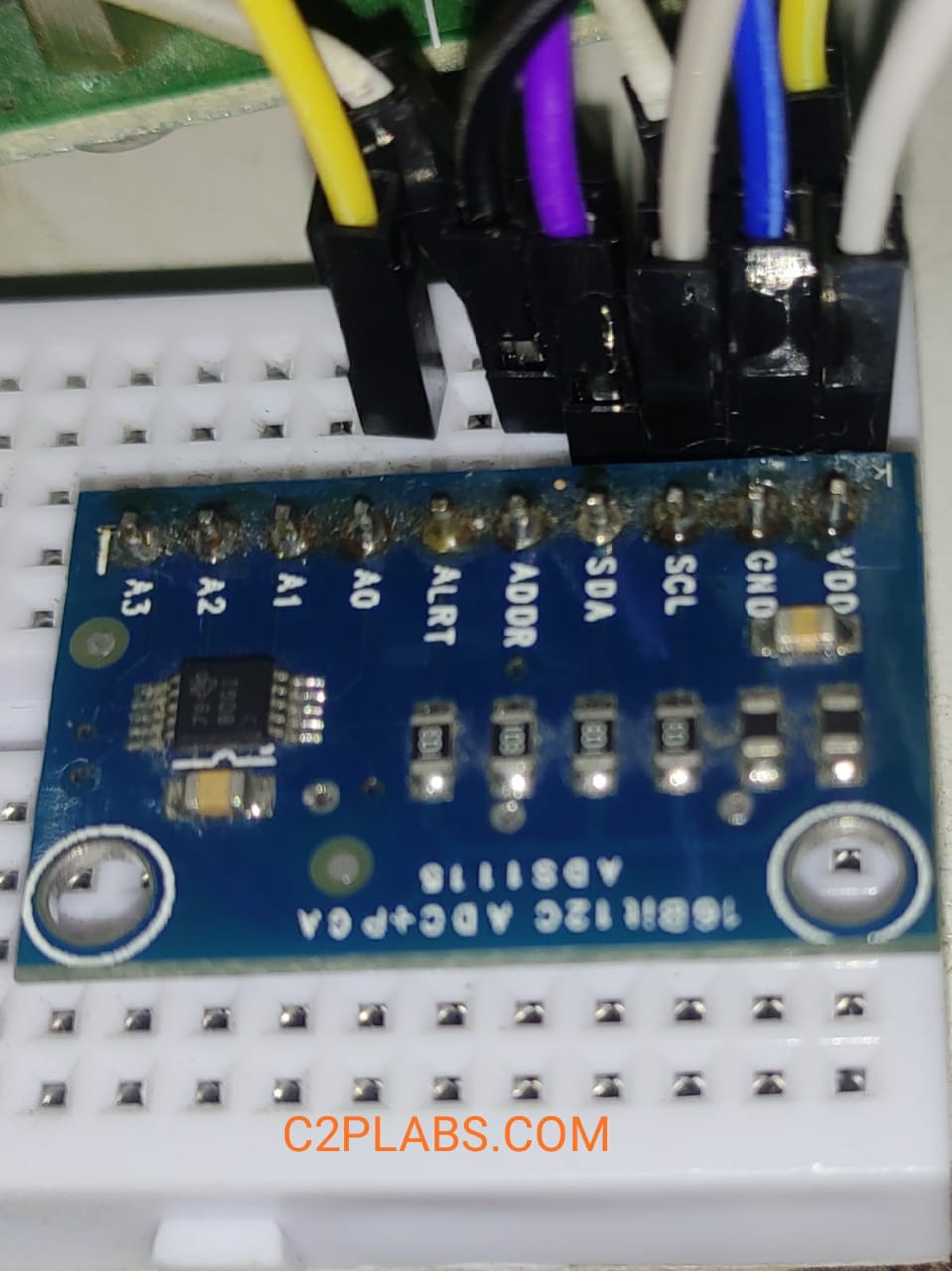
Interfacing any sensor which gives analog voltage output with Raspberry Pi requires external ADC (analog to digital converter) as BCM SOC used for RPi doesn’t have on chip ADC. This blog explains interfacing ADS1115 analog to digital converter(ADC) with Raspberry Pi. ADS1115 is provides I2C interface to interact with microcontroller. We are using ads1115 adc module from https://www.adafruit.com/product/1085. Pin out of ads1115 module is as shown in below fig.
PIN1->VDD Supply
PIN2->GND
PIN3 & PIN4 ->SCL., SDA I2C pins
PIN5->ADDR (address selection)
PIN6->ALRT (Alert Pin) This pin can used to generate interrupt when voltage reaches threshold value in compactor mode.
PIN7,8,9,10-> Analog input channels (A0 to A3).
This chip supports different I2C address based on configuration of ADDR (PIN5) pin. This addressing is useful when multiple ads111 devices are connected to same I2C master. When ADDR pin connected to GND, I2C address is 0x48, when it is connected to VDD the address is 0x49, When connected to SDA address is 0x4A and 0x4B when connected to SCL.
Connection to Raspberry Pi:
Enable I2C on Raspberry Pi:
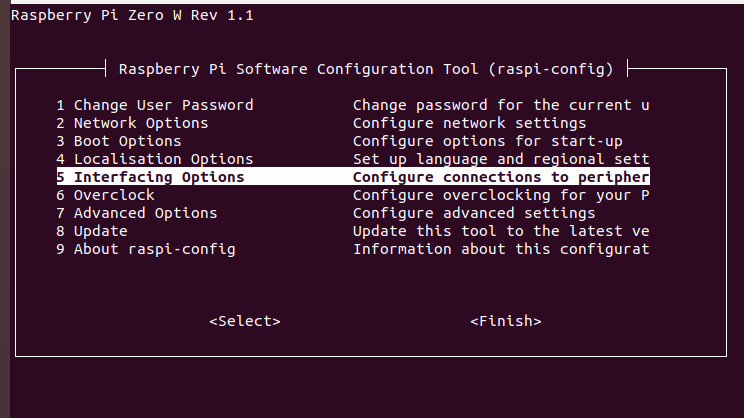
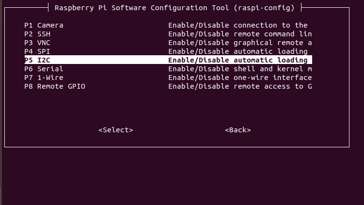
To enable I2C interfacing on Raspberry Pi, using rasp-config, we can enable it. open Raspberry software configuration using sudo raspi-config, this will open screen as shown below.
Linux i2c-tools contains i2cdetect command, this can be used to scan i2c bus masters available on the system. The output of sudo i2cdetect -l show the I2C device number and chipset name etc.
pi@raspberrypi:~$ sudo i2cdetect -l
i2c-1	i2c       	bcm2835 (i2c@7e804000)          	I2C adapter

Once we get the bus master details and its device number, we can sacn in the slaves connected using i2cdetect -y 1

pi@raspberrypi:~$ sudo i2cdetect -y 1
     0  1  2  3  4  5  6  7  8  9  a  b  c  d  e  f
00:          -- -- -- -- -- -- -- -- -- -- -- -- --
10: -- -- -- -- -- -- -- -- -- -- -- -- -- -- -- --
20: -- -- -- -- -- -- -- -- -- -- -- -- -- -- -- --
30: -- -- -- -- -- -- -- -- -- -- -- -- -- -- -- --
40: -- -- -- -- -- -- -- -- 48 -- -- -- -- -- -- --
50: -- -- -- -- -- -- -- -- -- -- -- -- -- -- -- --
60: -- -- -- -- -- -- -- -- -- -- -- -- -- -- -- --
70: -- -- -- -- -- -- -- --
Above output shows that this bus has one I2C salve connected and its I2C address is 0x48, which is address of ADS1115 as discussed above.
Interfacing LM35 temperature sensor:
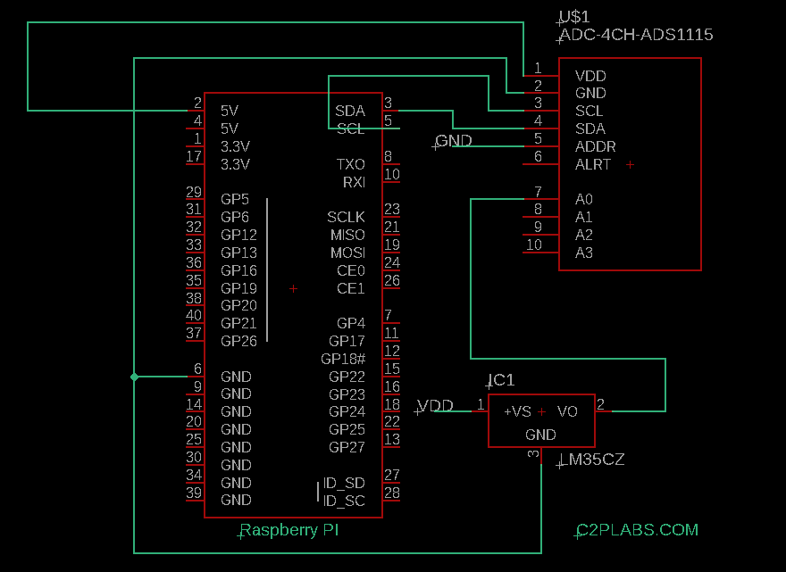
LM35 is analog temperature sensor with output voltage +10mv per every centigrade temperature. This has 3 pins VCC, GND and output pin. The output Pin of LM35 is connected to on of the Analog input (A0) of ADS1115 in our circuit.
C Program to read data from ADS1115 ADC:
#include <stdio.h>
#include <fcntl.h>
#include <linux/i2c-dev.h>

int i2c_fd =0;
char i2c_device_name[]="/dev/i2c-1";
char readbuff[2] = {0x00};
char writebuff[3] = {0x00};

int main()
{
	int ret;
	int i=0;
	i2c_fd = open(i2c_device_name,O_RDWR);
	short val;
	if(i2c_fd < 0){
		fprintf(stderr," I2C device file Open Error");
		return -1;
	}

	//Set client I2C address
	ioctl(i2c_fd,I2C_SLAVE,0x48);
	writebuff[0] = 0x01; //This byte is used to select the ADC registers 1-> For Config register 0->for Conversion
	writebuff[1] = 0xC3;
	writebuff[2] = 0x03;

	ret = write(i2c_fd,writebuff,3);

	for (i=0; i < 100; i++) { // Reading data contineously 100 times from ADS1115
        writebuff[0] = 0x01; //This byte is used to select the ADC registers 1-> For Config register 0->for Conversion
        writebuff[1] = 0xC3; //
        writebuff[2] = 0x03;

        ret = write(i2c_fd,writebuff,3);


	while (1) {

		ret=read(i2c_fd,readbuff,2);
		if(readbuff[0] & 0x80 )
			break;
	}

	writebuff[0]=0x00;
	ret = write(i2c_fd,writebuff,1);
	ret=read(i2c_fd,readbuff,2);
	val = readbuff [0] << 8 | readbuff[1];
	printf("\n0x%x ",val);
	}
	return 0;
}

