In the article I will show how to control DC motor using TB6612FNG H-bridge motor controller. This is a two channel motor driver small in size and doesn’t need heat sink . TB6612 has different voltage input pins for motor and logic. VM (motor voltage can be up to 15 V and Logic voltage can be 3,3V, this enables using this motor driver with Raspberry Pi family of microcontrollers.

TB6612FNG Breakout board Pinout:
- VM-VCC Motor is Supply voltage for motor: This can be up to max 15V.
- VCC Logic, this can be either 3.3V or 5V depending on the microcontroller logic voltage.
- STBY pin (Standby PIN) This should be active high to enable motor driver, this can be connected to logic supply or can be controlled from pi pico GPIO. We are connecting this to 3.3V
- Motor A Out1 and Out2 are A channel output pins to which DC motor is connected. I am using these two pins for connecting DC motor.
- IN1-A , IN2-A and PWM-A are control pins of channel A. These control pins are connected to raspberry pi pico GPIO pins 18, 17 and 16.
- IN1-B , IN2-B and PWM-B are control pins of channel B.
IN1 and IN2 are used to Stop, break and change the direction of the rotation and PWM pin is used to control the speed of DC motor.
In my wiring I have used IN1—GPIO18, IN2—GPIO17 and PWMA is connected to GPIO16 of Raspberry pi pico.
Pulse Width modulation (PWM):
PWM (Pulse width modulation) is method of generating variable average DC voltage using digital IO pins.
Using PWM microcontroller generate continuous train of pulses whose frequency and Active high time of pulse can be programmed. Frequency defines no of pulses per second.
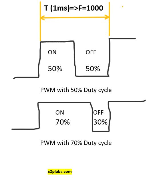
Duty cycle: Duty cycle defines the percentage of active high time of the pulse, the maximum amount of duty cycle is 100% which means always high pulse, minimum duty cycle is 0 which is continuous active low pulse.
In the above fig we can PWM pulses with 50% duty cycle and 70% duty cycle.
Micropython program:
from machine import Pin , PWM
from utime import sleep

led = Pin(25,Pin.OUT)
ina1 = Pin(18,Pin.OUT)
ina2 = Pin(17, Pin.OUT)
pwma = PWM(Pin(16))

pwma.freq(1000)

led.toggle()


def RotateCW(duty):
    ina1.value(1)
    ina2.value(0)
    duty_16 = int((duty*65536)/100)
    pwma.duty_u16(duty_16)

def RotateCCW(duty):
    ina1.value(0)
    ina2.value(1)
    duty_16 = int((duty*65536)/100)
    pwma.duty_u16(duty_16)

def StopMotor():
    ina1.value(0)
    ina2.value(0)
    pwma.duty_u16(0)


while True:
    duty_cycle=float(input("Enter pwm duty cycle"))
    print (duty_cycle)
    RotateCW(duty_cycle)
    sleep(5)
    RotateCCW(duty_cycle)
    sleep(5)
    StopMotor()
Detailed explanation of controlling can be seen at